
RESEARCH APPLICATION
Ultrasonic Electrospinning with a 60 kHz Focused Ultrasonic Nozzle
A 2025 US patent from Virginia Commonwealth University, US 12,421,630 B2, shows that a MicroSpray focused ultrasonic spray nozzle, turned tip-up and placed in a high-voltage field, becomes a needle-free electrospinning spinneret. Acoustic vibration forms a standing wave on the polymer meniscus, and fibers jet simultaneously from multiple wave peaks, producing sub-micron polyacrylonitrile fibers without multi-needle spinnerets.
The throughput problem in electrospinning
Electrospinning is a simple, low-cost route to fine and ultrafine polymer fibers for filtration media, separation membranes, drug-delivery patches, and tissue scaffolds. Its industrial weakness is throughput: a conventional spinneret has one capillary and emits one fiber jet at a time. Multi-needle heads raise output but demand perfectly uniform solution distribution to every needle and are difficult to manufacture consistently. Needle-free approaches generate fibers from the crests of a rippled liquid surface instead, but existing methods such as bubble electrospinning require injecting gas into the solution.
The VCU method: standing waves as spinnerets
US Patent 12,421,630 B2, Ultrasonic electrospinning for the production of fine and ultrafine fibers (inventor Daren Chen, assigned to Virginia Commonwealth University, filed Feb. 14, 2023, granted Sept. 23, 2025), takes a different route. The exit surface of an ultrasonic nozzle is vibrated so that the polymer solution on it forms a standing wave. With a voltage differential between the nozzle and a target, each wave peak acts as a jetting site, and multiple fibers are drawn at once. At higher acoustic power, cavitation creates gas bubbles that rise to the meniscus and add further jetting sites, without any bubble injection. Ultrasonic heating also lowers solution viscosity and surface tension, so jetting starts at a lower voltage.
The patent is explicit that this contradicts conventional thinking: ultrasonic nozzles, including those sold commercially by MicroSpray, were considered spraying devices only, not viable electrospinning implements.
How a standing wave becomes a spinneret
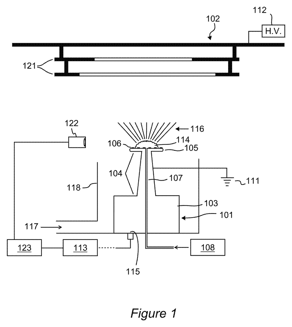
The nozzle exit surface is vibrated by an ultrasonic generator so the polymer solution on it forms a standing wave. With a voltage differential between the exit surface and a target, each wave peak becomes a jetting site and multiple fibers are drawn at once. At higher acoustic power, cavitation generates gas bubbles in the solution; vibration drives them quickly to the meniscus, where they create further irregular crests and jetting sites, without gas injection.
Ultrasonic heating lowers solution viscosity and surface tension, so jetting begins at lower voltage. Lower voltage reduces energy use, component stress, and the risk of reaching the arcing threshold of the surrounding gas. A feedback loop (camera plus controller) can monitor the standing wave and adjust vibration frequency to stabilize jetting positions.
The same capillary-wave physics governs spraying. In spray mode, acoustic perturbations in the liquid film drive capillary wave growth, ligament formation, and droplet breakup; in electrospinning mode, the electric field pulls fibers from the wave crests before breakup, so the capillary wave pattern defines the jetting sites. Capillary wavelength scales as (8πσ / ρf²)^(1/3): higher frequency shortens the wavelength and increases the number of crests per unit area. The patent's independent claim covers conducting liquid to the exit surface of an electrospinning nozzle, vibrating that surface so the liquid forms a standing wave, supplying a voltage differential to a target, and controlling both to induce fiber jetting from the wave peaks; frequencies from 18 kHz to several MHz are contemplated.
Experimental setup and results from the patent example
The working example in the patent used a MicroSpray focused ultrasonic spray nozzle operating at 60 kHz. Key configuration details:
- Nozzle: MicroSpray 60 kHz focused ultrasonic nozzle with air shroud
- Orientation: nozzle exit pointing up; polymer forms a convex meniscus on the tip
- Electrical: nozzle grounded; DC high voltage (15–20 kV) applied to the collector
- Nozzle-to-collector distance: 3.5–4 in. (about 90–100 mm)
- Collector: metal ring (5 in. central hole) hung from an insulated plate, for easy fiber harvesting
- Shroud air: used as a dry sheath to dry fibers in flight; nozzle tip protruded past the shroud exit to minimize focusing
- Feed: programmable syringe pump, 60 and 120 µL/min
- Polymer: polyacrylonitrile (MW 150,000) in DMF, 6–14 wt%
Results
Fiber diameters were measured by SEM and ImageJ. Size scaled with solution viscosity (polymer concentration) and with feed rate, giving a simple two-knob control over fiber diameter.
- 8 wt% PAN, 60 µL/min (18.5 kV): mean fiber diameter 0.33 µm (SD 0.08 µm)
- 10 wt% PAN, 60 µL/min: about 0.64 µm
- 14 wt% PAN, 60 µL/min: 1.26 µm (SD 0.27 µm)
Increasing the feed rate to 120 µL/min increased fiber size at every concentration, and multiple jets were observed from the rippled meniscus in each run (data summarized from US 12,421,630 B2, Fig. 14).
Where this leads
The patent targets filtration media, where finer fibers lower pressure drop at constant particle capture, and thin nanofiber layers on industrial cartridges improve reverse-pulse cleaning. The same approach applies to separation membranes, wound dressings and drug-delivery mats, biological scaffolds, and non-polymer nanofibers. Because a single nozzle produces multiple jets and nozzles can be arrayed, the method offers a route to scaling needle-free electrospinning with commercially available hardware.
Configuring a MicroSpray nozzle for electrospinning
The VCU example used a standard 60 kHz focused nozzle. Based on the patent's teaching, MicroSpray can supply nozzles configured for tip-up mounting, electrical isolation of the transducer from the high-voltage field, and sheath-air drying. Talk to an engineer about frequency selection (higher frequency shortens the capillary wavelength and increases the number of jetting sites), tip geometry, and feed options for your polymer system.
Technical white paper
Ultrasonic Electrospinning with a Focused Ultrasonic Nozzle. Needle-free production of sub-micron polymer fibers using a MicroSpray 60 kHz focused ultrasonic nozzle, as demonstrated in US Patent 12,421,630 B2: the method, the role of the ultrasonic nozzle, the experimental setup and results, and configuration guidance for laboratories adopting the approach. Download the white paper (PDF)
Patent at a glance
- US 12,421,630 B2, Ultrasonic electrospinning for the production of fine and ultrafine fibers
- Inventor: Daren Chen
- Assignee: Virginia Commonwealth University
- Filed: Feb. 14, 2023 (Appl. No. 18/168,961); granted: Sept. 23, 2025; 13 claims
- View on Google Patents · USPTO full text
Related pages
- Focused Nozzle, the nozzle type used in the patent example
- Liquid Delivery, syringe-pump feed for the µL/min flow rates the method uses
- Gas Diffusion Electrodes for CO₂ Electrolysis, another application note with a white paper
- Hybrid Perovskite Thermal-Insulation Films, the scale-up path from spin coating
- Spray Pyrolysis
Why a focused ultrasonic nozzle works here
- ✓A flat, vibrating exit surface. A MicroSpray nozzle delivers liquid through a large internal channel onto an atomizing tip driven by a Langevin transducer. That tip is exactly the vibrating exit surface the method needs, and the liquid sits directly on it.
- ✓Standing waves are the same physics as atomization. In spray mode, capillary waves on the liquid film grow until ligaments pinch off into droplets. In electrospinning mode, the electric field pulls fibers from the wave crests before droplet breakup, so the wave pattern itself defines the jetting sites.
- ✓The air shroud becomes a drying sheath. The focusing feature that normally narrows the spray pattern was repurposed to deliver dry sheath air that solidifies fibers in flight.
- ✓Non-clogging feed. Viscous polymer solutions that would block a fine capillary flow freely through the ultrasonic nozzle's feed channel.
- ✓Standalone component. The nozzle, generator, and syringe pump integrate into a custom rig with a laboratory HV supply; no proprietary platform is required.
References
The patent and its pre-grant publication. Data on this page are summarized from the published patent; MicroSpray was not involved in the VCU research.
- Ultrasonic electrospinning for the production of fine and ultrafine fibers
D. Chen
US Patent 12,421,630 B2, assigned to Virginia Commonwealth University (filed Feb. 14, 2023; granted Sept. 23, 2025) ·
The working example used a MicroSpray 60 kHz focused ultrasonic nozzle.
- Ultrasonic electrospinning for the production of fine and ultrafine fibers (pre-grant publication)
D. Chen
US 2024/0191400 A1 ·
Recommended Equipment
Focused Nozzle
The nozzle type used in the patent's working example: 60 kHz with the air-shroud focusing feature, here repurposed as a drying sheath; 120 kHz shortens the capillary wavelength for more jetting sites
View details →Liquid Delivery (Syringe Pump)
Programmable syringe-pump feed at tens to hundreds of µL/min, matched to polymer viscosity; the example ran at 60 and 120 µL/min
View details →Common Questions from Research Groups
Can an ultrasonic spray nozzle be used for electrospinning?
Yes. The VCU patent demonstrates needle-free electrospinning with a MicroSpray 60 kHz focused nozzle mounted tip-up in a 15–20 kV field. Fibers jet from multiple peaks of the acoustically driven standing wave on the meniscus.
What fiber sizes were produced?
Mean diameters from about 0.33 µm (8 wt% PAN) to about 1.26 µm (14 wt% PAN) at 60 µL/min, increasing with polymer concentration and feed rate.
Does the high voltage damage the nozzle?
In the example the nozzle was grounded and the voltage applied to the collector, protecting the transducer and generator. The patent also describes assemblies that allow the voltage to be applied at the nozzle instead.
Configuring a nozzle for electrospinning?
MicroSpray can supply focused nozzles configured for tip-up mounting, electrical isolation of the transducer from the high-voltage field, and sheath-air drying. Tell us your polymer system, target fiber size and feed rate and we will recommend a frequency and tip geometry.