
ENERGY APPLICATION
Solar Cell Coating
Ultrasonic spray deposition of solution-processed photovoltaic layers — organic donor-acceptor absorbers, metal-halide perovskite precursors, TiO₂ and SnO₂ electron-transport layers, hole-transport polymers, and kesterite CZTS films — with the wetting, drying, and surface-chemistry control that turns a sprayed liquid into a device-quality thin film.
The Challenge
Across the published literature on spray-coated solar cells, one finding repeats: successful device fabrication is never attributed to atomization alone. A working photovoltaic layer demands coordinated control of ink formulation, droplet generation, surface wetting, solvent evaporation, crystallization, layer thickness, interface compatibility, and post-deposition treatment. Spin coating cannot scale beyond small rigid substrates, while pneumatic spraying delivers a broad droplet-size scatter at high momentum that disrupts wet-film leveling and damages fragile underlying layers in a multilayer stack.
Our Solution
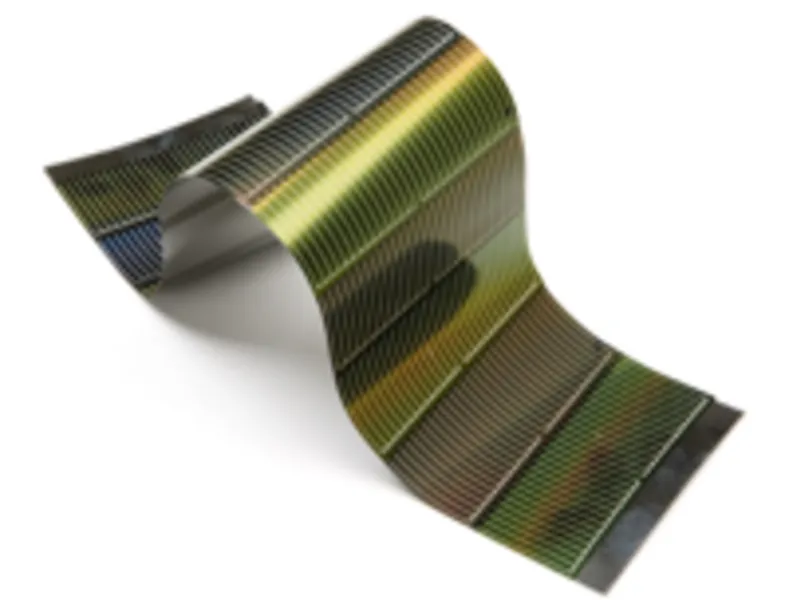
MicroSpray ultrasonic nozzles produce a fine, low-momentum mist whose droplet size is set by operating frequency rather than air pressure, so the spray arrives soft enough to coalesce into a continuous wet film on textured, flexible, or even curved substrates. Integrated into an automated motion platform with calibrated liquid delivery, the same nozzle deposits every solution-processable layer in the stack — absorber, electron-transport, and hole-transport — and the literature shows fully spray-coated perovskite cells reaching a reported 19.4% reverse-scan efficiency in small-area devices. The nozzle is best understood as the core of a modular deposition platform, not a single-layer laboratory tool.
Spray Chemistry as Surface Modification: Wetting, Drying, and Crystallization
Every sprayed layer in a solar cell is an exercise in surface modification: an atomized ink lands on a prepared surface, wets it, dries, and converts into a new solid surface with different chemistry, energy, and electronic behavior — which then becomes the substrate for the next layer. The receiving surface must be clean and sufficiently high in surface energy for neighboring droplets to merge, which is why degreasing is normally followed by ultraviolet-ozone or oxygen-plasma activation. Too little surface energy produces dewetting, pinholes, and electrical shunts; too much encourages edge accumulation and uncontrolled lateral flow. The practical target is a reproducible contact angle that lets droplets coalesce without flooding the surface.
The strongest theme across the peer-reviewed studies is that atomization establishes the initial liquid distribution, but drying determines the final microstructure. Droplets must arrive wet enough to coalesce yet evaporate quickly enough to prevent large-scale liquid movement. Premature airborne drying produces powdery, poorly adherent deposits; excessively slow evaporation causes flooding, solute migration, and nonuniform crystallization. Perovskite absorbers are especially sensitive because solvent removal happens simultaneously with nucleation and crystal growth — published methods manage it with heated substrates, thermal annealing, vacuum-assisted drying, antisolvent exposure, or rapid photonic curing for low-thermal-budget flexible substrates.
This is where low-momentum ultrasonic atomization earns its place in the stack. Because droplet size is governed by nozzle frequency rather than air pressure, the spray delivers a narrow droplet population at near-zero velocity, so the wet film's behavior on the surface is set by deliberately chosen variables — substrate temperature, solvent composition, pass overlap — instead of by uncontrolled droplet scatter and impact momentum. Each subsequent layer's solvent must also leave the layer below intact, so multilayer devices are built from orthogonal solvent systems with controlled drying between passes.
References for this section
- High-Performance Flexible Perovskite Solar Cells by Using a Combination of Ultrasonic Spray-Coating and Low Thermal Budget Photonic Curing — S. Das, et al., ACS Photonics () Free copy (author version) →
- Two-Step Ultrasonic Spray Deposition of CH₃NH₃PbI₃ for Efficient and Large-Area Perovskite Solar Cell — H. Huang, et al., Nano Energy ()
- Ultrasonic Spray-Coated Mixed Cation Perovskite Films and Solar Cells — Y.-S. Chou, et al., ACS Sustainable Chemistry & Engineering ()
Ultrasonic Spray Deposition in Thin-Film Solar Cell Manufacturing
The sections below summarize recurring process findings from seventeen peer-reviewed studies of spray-coated photovoltaics — organic, perovskite, and kesterite device platforms — spanning 2009 to 2023. Reported efficiencies and process conditions are study-specific and should not be read as universal operating specifications. Each study is cited directly beneath the section its findings support, with links to the publisher's site.
Which Solar Cell Layers Can Be Spray-Deposited?
The literature demonstrates an ultrasonic nozzle at nearly every position in a solar-cell stack. Organic photovoltaic studies sprayed the P3HT:PCBM donor-acceptor photoactive blend. Perovskite studies deposited single-cation, mixed-cation, triple-cation, and lead-free double-perovskite (Cs₂AgBiBr₆) absorbers, while related work used the same platform for TiO₂ and SnO₂ electron-transport layers and spiro-OMeTAD hole-transport layers. Kesterite research sprayed CZTS as either nanocrystal dispersions or molecular precursor inks. One fully spray-coated study deposited the SnO₂ transport layer, the triple-cation absorber, and the hole-transport layer all by spray, reporting 19.4% reverse-scan efficiency in small-area cells.
References for this section
- Ultrasonic Spray Deposition for Production of Organic Solar Cells — K. X. Steirer, et al., Solar Energy Materials and Solar Cells ()
- Copper-Zinc-Tin-Sulfide Thin Films via Annealing of Ultrasonic Spray Deposited Nanocrystal Coatings — B. A. Williams, et al., ACS Applied Materials & Interfaces ()
- Fully Spray-Coated Triple-Cation Perovskite Solar Cells — J. E. Bishop, et al., Scientific Reports () Open access · no paywall
- Spray-Coated Lead-Free Cs₂AgBiBr₆ Double Perovskite Solar Cells with High Open-Circuit Voltage — N. Daem, et al., Solar RRL () Open access · no paywall
- Ultrasonic Spray Coating of Kesterite CZTS Films from Molecular Inks — P. R. Ghediya, et al., Applied Physics A () Free copy (author version) →
Ink Formulation and Liquid Delivery
A photovoltaic ink must stay chemically stable while also atomizing, wetting, drying, and converting into the intended electronic material. The critical properties are solids concentration, viscosity, surface tension, density, solvent volatility, particle size, dispersion stability, and resistance to precipitation at the feed line or nozzle. Perovskite inks carry lead or silver-bismuth halides, ammonium halides, and cesium salts in polar solvents; organic inks use aromatic solvents; oxide transport layers use nanoparticle dispersions. Filtration, inert tubing, chemically compatible seals, and low-dead-volume plumbing are essential parts of the coating system. Several studies also demonstrate concurrent pumping — metering separate precursor solutions independently and combining them near the atomizing zone — so donor-to-acceptor ratio, halide composition, or solids loading can be changed without preparing a new bulk ink for each condition.
References for this section
- Concurrently Pumped Ultrasonic Spray Coating for Donor:Acceptor and Thickness Optimization of Organic Solar Cells — J. G. Tait, B. P. Rand, P. Heremans, Organic Electronics ()
- Rapid Composition Screening for Perovskite Photovoltaics via Concurrently Pumped Ultrasonic Spray Coating — J. G. Tait, et al., Journal of Materials Chemistry A () Free copy (author version) →
Substrate Preparation, Surface Energy, and Wetting
Typical substrates include fluorine-doped tin oxide (FTO) glass, indium tin oxide (ITO) glass, molybdenum-coated soda-lime glass, and ITO-coated flexible polymer films. Degreasing and particulate removal are normally followed by UV-ozone or oxygen-plasma surface activation when the substrate and underlying layers permit it. Poor cleaning or insufficient activation produces dewetting, pinholes, local thickness loss, and electrical shunts; excessive wetting encourages edge accumulation and uncontrolled lateral flow. The objective is a reproducible contact angle that allows neighboring droplets to merge without flooding the surface.
References for this section
- Ultrasonic Spray-Coating of Large-Scale TiO₂ Compact Layer for Efficient Flexible Perovskite Solar Cells — P. Zhou, et al., Micromachines () Open access · no paywall
Controlling Atomization and Coating Motion
The main adjustable variables are liquid flow rate, ultrasonic frequency and power, nozzle-to-substrate distance, shaping-gas flow, traverse speed, raster spacing, substrate temperature, and pass count — and they interact. A key finding: ultrasonic power must be high enough for stable atomization but should not be used as the primary thickness control. Thickness is more reliably set by calibrated liquid delivery, motion speed, raster overlap, and number of passes. Multiple light passes beat one heavily flooded pass, because incremental deposition reduces runoff and allows partial solvent removal between layers — but each pass must still overlap the previous track while wet enough to level, or banding and rough boundaries result.
References for this section
- Controlled Deposition and Performance Optimization of Perovskite Solar Cells Using Ultrasonic Spray-Coating of Photoactive Layers — W.-C. Chang, et al., ChemSusChem ()
- Scalable Ultrasonic Spray-Processing Technique for Manufacturing Large-Area CH₃NH₃PbI₃ Perovskite Solar Cells — L.-H. Chou, et al., ACS Applied Materials & Interfaces ()
Layer Integration and Solvent Compatibility
A multilayer device needs more than independently optimized coatings. Each new solvent must be compatible with the layer below — a later pass must not dissolve, swell, delaminate, or chemically reduce the previously deposited film. Successful stacks use orthogonal solvent systems, controlled drying between layers, and surface treatments that preserve electronic interfaces. Charge-selective layers must be continuous enough to prevent direct absorber-electrode contact yet thin enough to avoid excess series resistance, and the absorber must give complete pinhole-free coverage.
References for this section
- Ultrasonic Spray Deposition of TiO₂ Electron Transport Layers for Reproducible and High Efficiency Hybrid Perovskite Solar Cells — J. Sun, et al., Solar Energy () Free copy (author version) →
- Sequential Ultrasonic Spray-Coating Planar Three Layers for 1 cm² Active Area Inverted Perovskite Solar Cells — L.-H. Chou, et al., Energy Technology ()
Quality Control and Scale-Up
Process qualification spans wet-film behavior and finished-device properties: viscosity and surface tension, flow-rate calibration, spray-width mapping, film-thickness uniformity, surface roughness, crystal structure, pinhole density, sheet resistance — then open-circuit voltage, short-circuit current density, fill factor, power-conversion efficiency, and device-to-device variation. Statistical design-of-experiments methods outperform one-factor-at-a-time adjustment because temperature, speed, pass count, flow, and solvent composition frequently interact. Scale-up means holding stable mass-per-area delivery over larger width and longer runs; the literature shows ultrasonic spray coating flexible sheets, centimeter-scale active areas, and curved surfaces, though efficiency commonly decreases as area increases — underscoring the need for thickness mapping and uniform thermal management. Lead-containing perovskite processing additionally requires enclosed spraying, filtered exhaust, and validated waste handling.
References for this section
- Nonplanar Spray-Coated Perovskite Solar Cells — T. Thornber, et al., ACS Applied Materials & Interfaces () Open access · no paywall
- Investigating the Fabrication of Perovskite Solar Cells by Ultrasonic Spray Coating: A Design of Experiments Approach — J. Silvano, et al., ACS Applied Energy Materials () Free copy (author version) →
A Worked Example: Spraying the P3HT:PCBM Absorber Layer
A 2009 study from the National Renewable Energy Laboratory and the Colorado School of Mines shows the method step by step. The P3HT:PCBM absorber was sprayed inside a nitrogen glovebox with a 120 kHz ultrasonic nozzle, a mass-flow-regulated carrier gas and a metering pump: 2 mg/mL ink at 0.33 mL/min, 7 L/min of carrier gas, the nozzle 5 cm above a substrate held at 25 °C. Fifty passes of about 11 nm each built a 0.55 µm active layer, and two final passes at double the flow rate smoothed the surface. Single droplets dried as rings, so coverage came from overlap, and coffee-stain texture was still visible after fifty passes. Solvent choice decided the outcome. Chlorobenzene ink gave cells of 3.0% after annealing and 3.2% with the smoothing passes, close to the spin-coated cells of the period; p-xylene ink formed large crystallites and reached 0.1% at room temperature, or 1.2% with the substrate heated to 78 °C. Annealing improved every device, mainly through higher current.
References for this section
- Ultrasonic Spray Deposition for Production of Organic Solar Cells — K. X. Steirer, et al., Solar Energy Materials and Solar Cells ()
Why Ultrasonic Spray?
- ✓Low material waste — fine, targeted atomization instead of overspray losses
- ✓Programmable thickness via calibrated flow, motion, overlap, and pass count
- ✓Low-momentum droplets preserve fragile underlying layers in multilayer stacks
- ✓Concurrent pumping enables rapid composition screening without new bulk inks
- ✓One nozzle platform deposits absorber, electron-transport, and hole-transport layers
- ✓Compatible with rigid glass, flexible polymer films, and nonplanar substrates
- ✓No vacuum requirement — solution processing in air or inert enclosure
- ✓Scales from small research cells to larger-area automated deposition
Recommended Equipment
Vortex Nozzle
Wide spray pattern for uniform coverage across large-area solar cell substrates
View details →SprayBlade™ Air Knife
Linear spray pattern for roll-to-roll and inline panel coating processes
View details →Liquid Delivery (Dosing Pump)
Pulse-free metered feed — the calibrated liquid delivery the literature identifies as the real thickness control
View details →Common Questions from Research Groups
Which layers of a solar cell can be deposited with an ultrasonic spray nozzle?
Published work covers nearly the whole solution-processable stack: organic P3HT:PCBM photoactive blends; single-, mixed-, and triple-cation perovskite absorbers plus lead-free Cs₂AgBiBr₆ double perovskites; TiO₂ and SnO₂ electron-transport layers; spiro-OMeTAD and conductive-polymer hole-transport layers; and kesterite CZTS absorbers from nanocrystal dispersions or molecular precursor inks. The nozzle is best treated as a modular deposition platform rather than a single-layer tool.
How is coating thickness controlled in ultrasonic spray deposition?
Not primarily with ultrasonic power — that only needs to be high enough to keep atomization stable. The literature consistently establishes thickness through calibrated liquid delivery, traverse speed, raster overlap, and pass count. Multiple light passes are favored over one flooded pass because incremental deposition reduces runoff and allows partial solvent removal between layers.
Can a perovskite solar cell be made entirely by spray coating?
Yes — one published study deposited the SnO₂ electron-transport layer, the triple-cation perovskite absorber, and the hole-transport layer all by ultrasonic spray, reporting a 19.4% reverse-scan efficiency in small-area cells. As with all published results, that figure is study-specific; efficiencies commonly decrease as active area increases, which is why thickness mapping and uniform thermal management matter during scale-up.
What surface preparation do substrates need before spray deposition?
Degreasing and particulate removal, normally followed by UV-ozone or oxygen-plasma activation when the substrate and underlying layers allow it. The goal is a reproducible contact angle: enough surface energy that neighboring droplets merge into a continuous wet film, but not so much that the ink floods laterally or accumulates at edges. Insufficient activation shows up as dewetting, pinholes, and electrical shunts.
Why does drying matter more than atomization for film quality?
Atomization only sets the initial liquid distribution — drying determines the final microstructure. Droplets must arrive wet enough to coalesce yet evaporate fast enough to prevent large-scale liquid movement. Perovskites are the extreme case because solvent removal coincides with nucleation and crystal growth; published processes manage it with heated substrates, thermal annealing, vacuum-assisted drying, antisolvent exposure, or photonic curing on low-thermal-budget flexible substrates.
Can ultrasonic spray coating handle flexible or curved solar cells?
Yes. The literature includes high-performance flexible perovskite cells on ITO-coated polymer film (paired with photonic curing to respect the polymer's thermal budget) and nonplanar spray-coated perovskite cells on curved surfaces — geometries that spin coating cannot address. Because the mist is low-momentum and conformal, the same process window developed on glass transfers to these substrates with adjusted drying conditions.
Developing a spray-deposited photovoltaic process? Contact us about nozzle selection, liquid delivery, and process feasibility.
Let's discuss your specific coating requirements.